Sculpting The Black Max, Part 2
This is part 2 in a WIP series of how I digitally sculpt mecha in Rhino3D, a CAD program I've been using for a while, now.
This was an old project that I've blown the dust off, and will update. On we go with part deux...
-------------------------------
>Initial
view in Rhino.
I’m
used to making things oriented to a certain scale. Scales are those
fractions you see on the side of model kit boxes. 1/48th
scale means your model is 48 times as small as the real deal.
I like
working to 1/100th
scale, in which case the model is 100 times as small as the
theoretical piece upon which it is based.
You also hear this scale
referred to as “15mm” scale when talking to miniature wargamer
types.
In
a perfect world, what you prototype for one scale should be able to
be translated without fear into another scale.
Experience has taught
me, however, that what you do initially in one scale is often
tailored for the intended machine upon which your build will be
produced, and for the final scale that the client wants.
Scaling a
build down often causes you to lose intricate details as they are
smooshed down to a smaller size.
Likewise, a detail that looked
perfect at a smaller size fails to hold the same complexity or visual
sharpness once a small build is made larger.
Thus, I try and orient
my detailed bits to a certain final size. If a client wants to make
a build larger and smaller later, I often advise them to give me
another crack at it so detailing can be optimized for their new
intended size.

All
long-windedness aside, I import the final picture above into Rhino,
making it the background line art to my Right side view. I must now
scale the art so that my build is oriented to be a 1/100th
scale model.

I
then move the picture to align the bottom of the feet with the red
line running along the bottom of the Right side view. This is my Y
axis “zero line”.
As you can see, I have a couple of
little guys already prototyped in Rhino. One is a standing, 6 foot
tall man. The other is a seated figure in a cockpit and ejection
seat. These are pre-made figures that I don’t necessarily
incorporate into my builds, but rather, I use them as size gauges,
ensuring that my builds will pass the “a human fits in these
things” test. I call these humanoid size gauges “Waldos.”
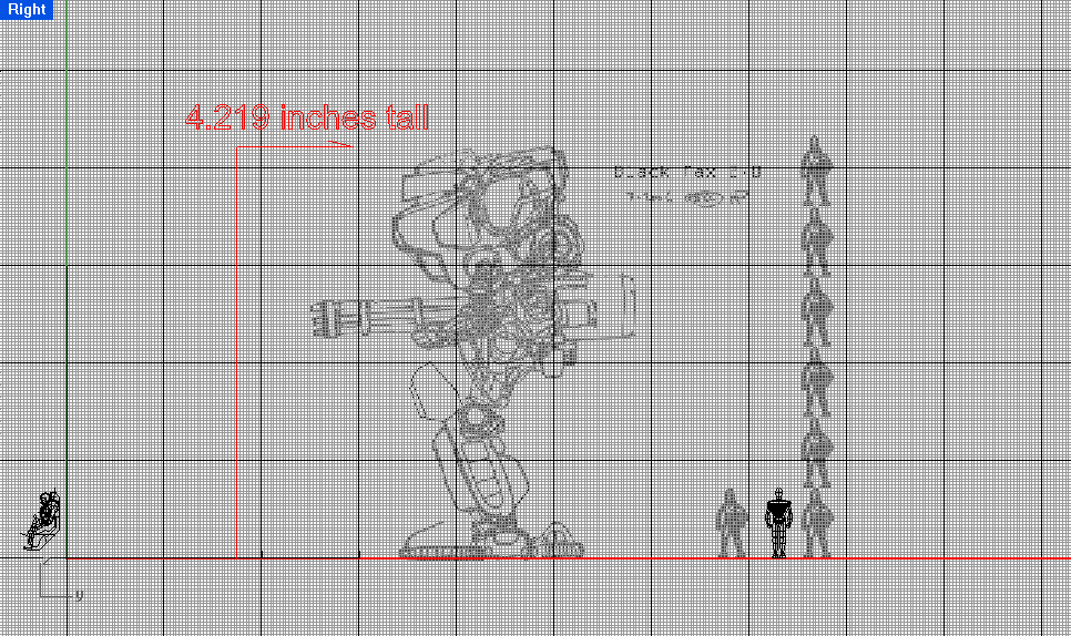
Now
that things are aligned, you can see that the drawn humans are taller
than the prototyped human, or Waldo. Thus, I scale the drawing so
that they are equal in height. Accordingly, the Black Max is brought
into scale as well.
Now,
a little math. 36 feet tall, the desired height of the Black max, is
432 inches. Since we are making a 1/100th
scale model, we divide 432 inches by 100. That gives us 4.32 inches.
I scaled the drawing pilot to my existing Waldo, though I could have
just drawn a reference line at 4.32 inches, and scaled the mech to
that. As you can see above, the Black Max has been scaled to 4.219
inches in height. Close enough.

I’ve used crude
maquettes, or Waldos, as stand-ins for years.
Just
to give you a close-up of the Waldos, here’s the standing Waldo.
He stands .72 inches tall, or 6 feet times 12 inches, divided by 100.

And here is a perspective shot of a
seated Waldo in his mock-up cockpit. The detail is rudimentary, but
he’s not a finished showpiece, only a digital tool I use for sizing
purposes.

I
line up the seated Waldo with the line art, roughly where I want him
to be seated inside the hull.

I
then “insert” him in front of the line art. The art isn’t
affected by anything prototyped on top of it, and basically performs
the same function as the wallpaper on your desktop.
Now I get to building. Prototyping a
mecha like the Black Max is going to be an exercise in
ultra-detailing, and will be performed in a number of waves or
cycles.
First, I’ll be tracing over the line
art, forming simple shapes and outlines.
Then, I will “bulk out” those
lines, and make general hull shapes and arrangements. This is not an
exact science, as the source art is just a guide. Thus, if I decide
I want some configurations to work out differently, I just make my
lines exactly how I want them. These changes sometimes happen on the
fly, or are a result of new techniques surpassing old source art (I
have stuff that’s 15 to 20 years old that has been waiting for
technology to catch up with my mechanized visions).
Next, a preliminary level of detailing
reveals what will and won’t work, and if any reworking is needed.
Finally, I take every piece, give it a
heavy amount of detailing, and finish each piece until the whole
thing clogs my computer with its massive demand for RAM.
So, let's start the tracing over the line art...

I begin lining out the foot and lower
leg. To differentiate my prototyping from the source art, I’ve made
everything that I prototype the color blue.

I then line out the main hull and tiny
T-Rex arm.

Obviously,
things are going to get messy in that area, so I’ll select the
T-Rex arm…

…and
move it off to the side.

I
also move the main hull off to join the T-Rex arm.

With the first two line-outs removed,
I then line out the main rotary cannon. Note that the straight
barrels don’t line up with the sagging line-art barrels. Such is
life.

I then finish off the thigh. It’s
still a little skinny for my taste, but that will change. Everything
is now ready to be bulked out into rough shapes and initial armor
configurations.
Well,
that wraps up Part Two of this little exercise in mecha design.
Part Three will deal with the initial bulk-out process, starting with the
Main Weapon Arms. Stay tuned.
Best,
John Bear Ross
Comments